

NaN / 0
Self-supporting SM G.655 48 Core Adss Fiber Optical Cable Manufacturers adss fiber optic cable 48 core
Get Latest Price
US$ 0.15
≥305 Meters
Quick Details
Brand Name:
Owire/OEM/ODM
Place of Origin:
Guangdong, China
Fiber Optic Cable Name:
SM ADSS Optical Cable
Fiber Optic Cable Model:
1167
Product Details
Wholesales Loose Tube Stranded G.652 GYFTCY SM ADSS Optical Cable
Product Description
ADSS Cable Description:
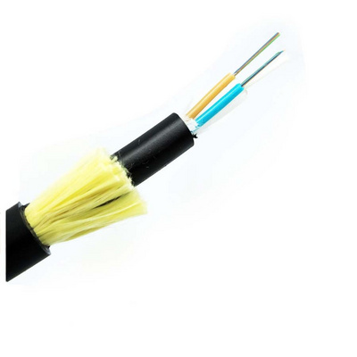
ADSS Cable is loose tube stranded. Fibers 250μm are positioned into a loose tube made of high modulus plastics. The tubes are filled with a water-resistant filling compound. The tubes and fillers are stranded around a FRP(Fiber Reinforced Plastic) as non-metallic central strength member into a compact and circular cable core. After the cable core is filled with compound. It is covered with thin PE(Polyethylence) inner sheath. After stranded layer of aramid yarns are applied over the inner sheath. After stranded layer of aramid yarns are applied over the inner sheath as strength member,the cable is completed with PE or AT(Anti-tranking) outer sheath.
ADSS Cable Characteristic
1.Cable be installed without shutting off the power;
2.Excellent AT performance.Maximum inductive at the operating point of AT sheath can reach 25KV;
3.Light weight and small diameter reducing the load caused by ice,wind,load on towers and backprops;
4.Large span lengths(Largest span is over 1000m)
5.Good performance of tensile strength and temperature;
6.Design life span is 30 years.
ADSS Cable
Standards
ADSS cable complies with Standard IEE P 1222&IEC60794-1
ADSS Cable
Applications
The actual status of overhead power lines is taken into full consideration when ADSS cable is being designed. For overhead power lines under 110KV,PE outer sheath is applied. For power lines equal to or over 110KV,AT outer sheath is applied. The dedicate design of aramid quantity and stranding process can satisfy the demand on various spans.
ADSS Cable Optical Characteristics
| G.652 | G.655 | 50/125μm | 62.5/125 μm | ||
| Attenuation(±20℃) | @850nm | ≤3.0dB/km | ≤3.0dB/km | ||
| @1300nm | ≤1.0dB/km | ≤1.0dB/km | |||
| @1310nm | ≤0.36dB/km | ≤0.4dB/km | |||
| @1550nm | ≤0.2dB/km | ≤0.23dB/km | |||
| Bandwidth(Class A) | @850nm | ≥500Mhz.km | ≥200Mhz.km | ||
| @1300nm | ≥1000Mhz.km | ≥600Mhz.km | |||
| Numerical Aperture | 0.200±0.015NA | 0.275±0.015NA | |||
| Cable Cut-off Wavelength λcc | ≤1260nm | ≤1480nm | |||
ADSS Cable Technical Parameters
| Ref. Outer Diameter(mm) | Ref. Weight kg/km | Ref. Daily Max Working Tension KN | Max Allowable Working Tension KN | Break Strength KN | Strength Member CSA mm 2 | Modulus Of Elasticity KN/ mm 2 | Heat Expansion Coefficient ×10 -6 /k | Suitable Span(NESC Standard,m) | ||||
| PE Sheath | AT Sheath | A | B | C | D | |||||||
| 12.5 | 125 | 136 | 1.5 | 4 | 10 | 4.6 | 7.6 | 1.8 | 160 | 100 | 140 | 100 |
| 13.0 | 132 | 142 | 2.25 | 6 | 15 | 7.6 | 8.3 | 1.5 | 230 | 150 | 200 | 150 |
| 13.3 | 137 | 148 | 3.0 | 8 | 20 | 10.35 | 9.45 | 1.3 | 300 | 200 | 290 | 200 |
| 13.6 | 145 | 156 | 3.6 | 10 | 24 | 13.8 | 10.8 | 1.2 | 370 | 250 | 350 | 250 |
| 13.8 | 147 | 159 | 4.5 | 12 | 30 | 14.3 | 11.8 | 1.0 | 420 | 280 | 400 | 280 |
| 14.5 | 164 | 177 | 5.4 | 15 | 36 | 18.4 | 13.6 | 0.9 | 480 | 320 | 160 | 320 |
| 14.9 | 171 | 185 | 6.75 | 18 | 45 | 22.0 | 16.4 | 0.6 | 570 | 380 | 550 | 380 |
| 15.1 | 179 | 193 | 7.95 | 22 | 53 | 26.4 | 18.0 | 0.3 | 670 | 460 | 650 | 460 |
| 15.5 | 190 | 204 | 9.0 | 26 | 60 | 32.2 | 19.1 | 0.1 | 750 | 530 | 750 | 510 |
| 15.6 | 194 | 208 | 10.5 | 28 | 70 | 33.0 | 19.6 | 0.1 | 800 | 560 | 800 | 560 |
| 16.3 | 211 | 226 | 12.75 | 34 | 85 | 40.0 | 20.1 | 0.1 | 880 | 650 | 880 | 650 |
| 16.8 | 226 | 242 | 15.45 | 41 | 103 | 48.0 | 24.0 | -0.4 | 1000 | 750 | 1000 | 760 |
| 17.2 | 236 | 253 | 16.2 | 45 | 108 | 51.0 | 25.1 | -0.5 | 1100 | 800 | 1100 | 830 |
| 17.9 | 249 | 266 | 18.0 | 50 | 120 | 58.8 | 26.1 | -0.8 | 1180 | 880 | 1180 | 900 |


Related Products

Our Services


