

NaN / 0
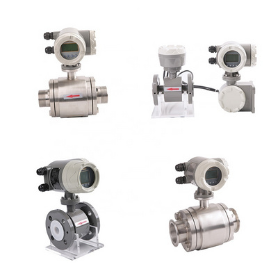
Factory Price DN32 Magnetic Flowmeter Industrial Sewage Mag Flow Meter Liquid Digital Water Electromagnetic Flow Meter
Get Latest Price
US$ 400
≥1 Bags
Quick Details
Type:
Variable Area Water Flowmeters, Variable Area Air & Gas Flowmeters, Variable Area Oil Flowmeters
Warranty:
12 months
Place of Origin:
Sichuan, China
Brand Name:
YND
Product Details
Overview
Electromagnetic flowmeter is a flow measurement instrument based on Faraday's law of electromagnetic induction, which can measure the volume flow rate of liquids with a certain conductivity. Due to its measurement accuracy not being affected by changes in the viscosity, density, temperature, and conductivity (above the allowable minimum limit) of the measured liquid, there are no components in the measuring tube that hinder liquid flow, so there is almost no pressure loss. By selecting appropriate materials for the insulation lining and measuring electrodes in the measuring tube, various corrosive (acid, alkali, salt, etc.) solution flow rates can be measured. Especially when measuring the flow rate of liquids containing solid particles such as mud, slurry, etc., its superiority is demonstrated. After matching with display and recording instruments, integrators or regulators, it can detect, accumulate, adjust and control the flow rate, and achieve long-distance signal transmission.
YND515 intelligent electromagnetic flowmeter is produced by introducing German advanced technology and assembling parts. It has the characteristics of advanced technology, stable performance, high measurement accuracy, convenient installation and no maintenance, and can be widely used in petroleum, chemical industry, metallurgy, mining, power, paper making, food, medicine, textile, and chemical industry
Fiber and other industrial fields.
1.1 Measurement principle:
The basic principle of electromagnetic flow meters is Faraday's law of electromagnetic induction, which states that a conductive liquid flowing in a magnetic field will generate an induced electromotive force. As shown in Figure 1, when the conductive liquid flows through the working magnetic field of the sensor, an electromotive force proportional to the volumetric flow rate is generated between the measuring tube wall and a pair of electrodes perpendicular to the flow direction and magnetic field direction. The magnitude of electromotive force can be expressed as follows:
E=K B D V
In the formula: E - Induced signal potential, V; K - constant; B - Magnetic induction intensity, T; D - inner diameter of measuring tube, m;
V - Average flow velocity in the axial direction of the electrode cross-section inside the measuring tube, m/s
The potential is then transmitted through a cable to a converter, which is amplified and converted into a standard
Current signal or frequency signal output.


