

NaN / 0
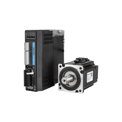
Lavichip CE certificate CANopen/ pulse high quality 750W close loop incremental 750W servo system
Get Latest Price
US$ 180
≥1 Sets
Quick Details
AC Voltage:
208-230 / 240 V
Warranty:
1 year
Place of Origin:
Guangdong, China
Brand Name:
Lavichip
Product Details
Product's details


Product's parameter
|
Parameters of driver
|
LYX-400W
|
LYX-750
|
LYX-1000
|
LYX-1500
|
LYX-2000
|
||||
|
Output power
|
400W
|
750W
|
1kW
|
1.5kW
|
2kW
|
||||
|
Rated output current
|
3
|
5.2
|
7.5
|
8
|
10
|
||||
|
Maximum current output
|
13
|
18.4
|
26.5
|
30.2
|
36
|
||||
|
Size
|
175*168*40
|
175*168*50
|
175*168*50
|
175*168*80
|
175*168*80
|
||||
|
Main loop and control loop power supply
|
Single phase220VAC-15%~+10%
|
|
|
|
|
||||
|
Control mode
|
IGBT SVPUM sine wave control
|
|
|
|
|
||||
|
Feedback mode
|
Bus encoder :RS485 communications
|
|
|
|
|
||||
|
Input pulse
|
0~500kHz, 5V differential mode; 0-200KHz, 24V single-ended mode
|
|
|
|
|
||||
|
Electronic gear ratio
|
1--8388608/1-8388608
|
|
|
|
|
||||
|
Input signal |
DI points :4 points (supports two modes of common cathode and common anode) can be allocated input signals: Service enable input (SRV-0N), Alarm free (A-CLR), Gain switching input (GAIN), Deviation counter clear input (CL), Instruction pulse disable input (INH), Internal instruction speed select 1 input (INTSPD1), Internal instruction speed select 2 input (INTSPD2), Internal instruction speed select 3 input (INTSPD3), Finger frequency switching input 1 (DIV), Command subitem frequency doubling switch input 2(DIV1), Forward drive disable input (FOT), Negative drive disable input (NOT), Speed symbol input (WC-SIGN), Torque command sign input(TC-SIGN), Forced alarm input (E-STOP) |
|
|
|
|
||||
|
Ouput signal |
Number of D0 points: 3 points (2 points single-ended output, 1 point double-ended output) Assignable output signals: service ready
output (S-RDY), external brake release signal (BRKOFF), positioning completion (INP), speed arrival output (AT-SPPED), alarm output (ALM), speed consistent output (V-COIN), position indication output (P-CMD), speed command output (V-CMD) |
|
|
|
|
||||
|
Encoder signal output
|
A phase, B phase, Z phase, long line drive output
|
|
|
|
|
||||
|
Alarm function
|
Overvoltage, undervoltage, overcurrent, overload, overheating, overspeed, main power input phase loss, abnormal regenerative
braking status, excessive position deviation, encoder feedback error, excessive braking rate, stroke overrun, EEPROM and so on |
|
|
|
|
||||
|
Operation and display
|
5 buttons, Five digital tube
|
|
|
|
|
||||
|
Debugging software |
Through the Lavichid debugging software, various parameters of the current loop, position loop, and speed loop can be adjusted,
the effective level of the input and output signals and the motor parameters can be changed, and the parameters can be imported and exported in the form of files, which is convenient for the driver to match with different motors or different loads: monitoring Waveforms such as speed and position error under trapezoidal wave test operation. |
|
|
|
|
||||
|
Communication function
|
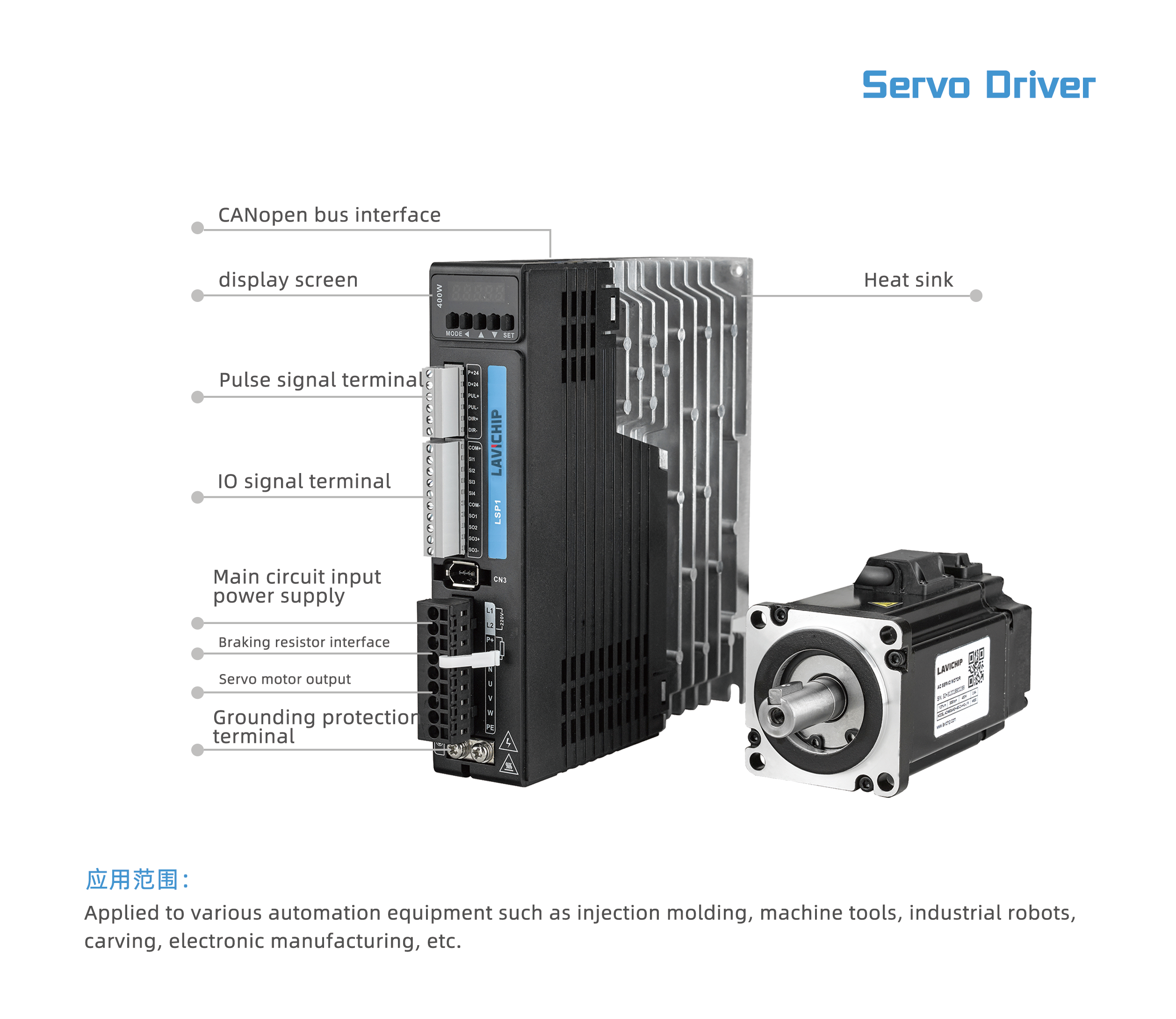
Support CANopen bus
|
|
|
|
|
||||
|
Braking mode
|
Built-in braking resistor (external connection is also available)
|
|
|
|
|
||||
|
Applicable load inertia
|
Less than 20 times the motor inertia
|
|
|
|
|
||||
|
Model of motor
|
Rated Power
|
Rated torque
|
Rated current
|
Moment of inertia
|
Rated speed
|
Maximum speed
|
Rated voltage
|
Encoder
|
Brake
|
|
|
(kw)
|
|
|
|
|
|
|
|
|
|
ACM2-04006OJA-30H13
|
|
|
|
|
3000
|
|
|
Single turn incremental |
Without
|
|
ACM2-04006SJA-30H13
|
|
|
|
|
|
|
|
|
With
|
|
ACM2-07508OJA-30H13
|
|
|
|
|
|
|
|
|
Without
|
|
ACM2-07508SJA-30H13
|
|
|
|
|
With
|
|
|
|
|
|
ACM2-1K008OJA-30H13
|
|
|
|
|
|
|
|
|
Without
|
|
ACM2-1K008SJA-30H13
|
|
|
|
|
With
|
|
|
|
|
Hot Searches


